
Learn ESP32 GPIO Pins, Power Pins, PWM Pins and Arduino IDE Setup
What is ESP32?
ESP32 is a powerful WiFi + Bluetooth enabled microcontroller board used in IoT, embedded systems, robotics and automation projects.
It supports digital input/output, analog reading, PWM output, touch sensors, WiFi communication and much more.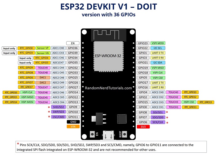
ESP32 GPIO Pins
GPIO means General Purpose Input Output pins. These pins can be used as input or output.
- GPIO 2 → Built-in LED in many ESP32 boards
- GPIO 4, 5, 18, 19 → Digital Input/Output
- GPIO 34, 35 → Input only pins
- GPIO 21, 22 → I2C Communication
- GPIO 23, 19, 18, 5 → SPI Communication
Power Pins
- 3V3 → 3.3V Output Pin
- VIN → Input Supply Voltage
- GND → Ground Pin
ESP32 works on 3.3V logic. Avoid giving 5V directly to GPIO pins.
PWM Pins
PWM (Pulse Width Modulation) is used to control LED brightness, motor speed and servo motors.
Most ESP32 GPIO pins support PWM functionality.
- GPIO 2
- GPIO 4
- GPIO 5
- GPIO 18
- GPIO 19
Install Arduino IDE
Step 1:
Download Arduino IDE from the official Arduino website.
Step 2:
Install the software normally like other applications.
Step 3:
Open Arduino IDE after installation.
Install ESP32 Board Package
Step 1:
Open Arduino IDE → Go to File > Preferences
Step 2:
Paste this URL in Additional Boards Manager URLs:
https://raw.githubusercontent.com/espressif/arduino-esp32/gh-pages/package_esp32_index.json
Step 3:
Go to Tools > Board > Boards Manager
Step 4:
Search ESP32 and click Install.
Install Required Libraries
Some projects require external libraries.
- DHT Sensor Library
- LiquidCrystal I2C
- WiFi Library
- ThingSpeak Library
Open:Sketch > Include Library > Manage Libraries
Search the library name and click Install.
Test ESP32 with LED Blink
Upload this simple LED blink code to test your ESP32 board.
void setup() {
  pinMode(2, OUTPUT);
}

void loop() {
  digitalWrite(2, HIGH);
  delay(1000);

  digitalWrite(2, LOW);
  delay(1000);
}