When it comes to the ESP32 chip specifications, you’ll find that:
- The ESP32 is dual core, this means it has 2 processors.
- It has Wi-Fi and bluetooth built-in.
- It runs 32 bit programs.
- The clock frequency can go up to 240MHz and it has a 512 kB RAM.
- This particular board has 30 or 36 pins, 15 in each row.
- It also has wide variety of peripherals available, like: capacitive touch, ADCs, DACs, UART, SPI, I2C and much more.
- It comes with built-in hall effect sensor and built-in temperature sensor.
Specifications – ESP32 DEVKIT V1 DOIT
| Number of cores | 2 (dual core) |
| Wi-Fi | 2.4 GHz up to 150 Mbits/s |
| Bluetooth | BLE (Bluetooth Low Energy) and legacy Bluetooth |
| Architecture | 32 bits |
| Clock frequency | Up to 240 MHz |
| RAM | 512 KB |
| Pins | 30 or 36 (depends on the model) |
| Peripherals | Capacitive touch, ADC (analog to digital converter), DAC (digital to analog converter), I2C (Inter-Integrated Circuit), UART (universal asynchronous receiver/transmitter), CAN 2.0 (Controller Area Netwokr), SPI (Serial Peripheral Interface), I2S (Integrated Inter-IC Sound), RMII (Reduced Media-Independent Interface), PWM (pulse width modulation), and more. |
ESP32 Pinout Guide
The ESP32 has more GPIOs with more functionalities compared to the ESP826.
With the ESP32 you can decide which pins are UART, I2C, or SPI – you just need to set that on the code. This is possible due to the ESP32 chip’s multiplexing feature that allows to assign multiple functions to the same pin. If you don’t set them on the code, the pins will be used as default – as shown in the figure below (the pin location can change depending on the manufacturer).
Version with 30 GPIOs

Version with 36 GPIOs

Installing ESP32 Add-on in Arduino IDE
To add ESP32 Board in your Arduino IDE, follow these instructions :
1. Open your Arduino IDE, go to File>Preferences
_jslbcbjCGZ.png?auto=compress%2Cformat&w=740&h=555&fit=max)
_7Gx3veRH5E.png?auto=compress%2Cformat&w=740&h=555&fit=max)
2. Put https://dl.espressif.com/dl/package_esp32_index.json into the “Additional Board Manager URLs” field as shown in the figure below. Then, click the “OK” button
_li_oZPQBsx9Q1.jpg?auto=compress%2Cformat&w=740&h=555&fit=max)
Note: if you already have another boards (i.e ESP8266 boards URL), you can separate the URLs with a comma like this:
https://dl.espressif.com/dl/package_esp32_index.json, http://arduino.esp8266.com/stable/package_esp8266com_index.json3. Then go to the Boards Manager. Go to Tools > Board > Boards Manager
_eSOvQvXBCw.png?auto=compress%2Cformat&w=740&h=555&fit=max)
4. Go to the search bar and type ESP32 then install ESP32 by Espressif Systems
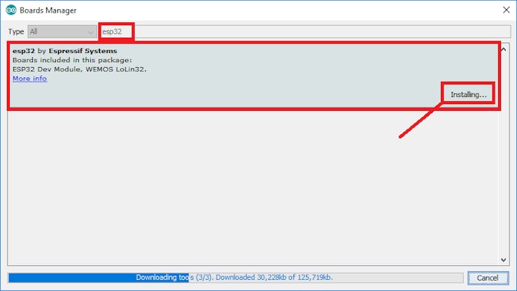
5. Wait a few seconds then you’ve installed it
_YxZCA46jI8.png?auto=compress%2Cformat&w=740&h=555&fit=max)
Note: Some cases will have an error message when downloading the add-on

Error message while downloading new boards
If you find this problem, go to File > Preferences then click on “C:\Users\Arbi\AppData\Local\Arduino15“
_O9o5t2A6mq.png?auto=compress%2Cformat&w=740&h=555&fit=max)
Delete all files in that directory and repeat from step 1 to 4.
_vcIMENqQFR.png?auto=compress%2Cformat&w=740&h=555&fit=max)
I have the same problem and it worked with this solution :). Let’s go to the next step
Testing your ESP32 Board
1. Open Arduino IDE and plug the ESP32 Board to your computer.
2. Select your Board in Tools > Board menu (in my case “DOIT ESP32 DEVKIT V1″)
_XLVx6wPG3P.png?auto=compress%2Cformat&w=740&h=555&fit=max)
3. Select the Communication Port, go to Tools > Port > (in my case it’s COM15)
_HZleqZjTpK.png?auto=compress%2Cformat&w=740&h=555&fit=max)
Basic LED COde
Upload Code to the ESP32 using Arduino IDE
To show you how to upload code to your ESP32 board, we’ll build a simple example to blink an LED.
Copy the following code to your Arduino IDE:
/*
  Blink
*/

// ledPin refers to ESP32 GPIO 23
const int ledPin = 23;

// the setup function runs once when you press reset or power the board
void setup() {
  // initialize digital pin ledPin as an output.
  pinMode(ledPin, OUTPUT);
}

// the loop function runs over and over again forever
void loop() {
  digitalWrite(ledPin, HIGH);   // turn the LED on (HIGH is the voltage level)
  delay(1000);                  // wait for a second
  digitalWrite(ledPin, LOW);    // turn the LED off by making the voltage LOW
  delay(1000);                  // wait for a second
}
How to Use I2C LCD with ESP32 on Arduino IDE (ESP8266 compatible)
This tutorial shows how to use the I2C LCD (Liquid Crystal Display) with the ESP32 using Arduino IDE. We’ll show you how to wire the display, install the library and try sample code to write text on the LCD: static text, and scroll long messages. You can also use this guide with the ESP8266.
16×2 I2C Liquid Crystal Display
For this tutorial we’ll be using a 16×2 I2C LCD display, but LCDs with other sizes should also work.
The advantage of using an I2C LCD is that the wiring is really simple. You just need to wire the SDA and SCL pins.
Additionally, it comes with a built-in potentiometer you can use to adjust the contrast between the background and the characters on the LCD. On a “regular” LCD you need to add a potentiometer to the circuit to adjust the contrast.

Wire your LCD to the ESP32 by following the next schematic diagram. We’re using the ESP32 default I2C pins (GPIO 21 and GPIO 22).

You can also use the following table as a reference.
| I2C LCD | ESP32 |
| GND | GND |
| VCC | VIN |
| SDA | GPIO 21 |
| SCL | GPIO 22 |
Display Static Text on the LCD
Displaying static text on the LCD is very simple. All you have to do is select where you want the characters to be displayed on the screen, and then send the message to the display.
Here’s a very simple sketch example that displays “Hello, World!“.
#include <LiquidCrystal_I2C.h>

// set the LCD number of columns and rows
int lcdColumns = 16;
int lcdRows = 2;

// set LCD address, number of columns and rows
// if you don't know your display address, run an I2C scanner sketch
LiquidCrystal_I2C lcd(0x27, lcdColumns, lcdRows);

void setup(){
  // initialize LCD
  lcd.init();
  // turn on LCD backlight
  lcd.backlight();
}

void loop(){
  // set cursor to first column, first row
  lcd.setCursor(0, 0);
  // print message
  lcd.print("Hello, World!");
  delay(1000);
  // clears the display to print new message
  lcd.clear();
  // set cursor to first column, second row
  lcd.setCursor(0,1);
  lcd.print("Hello, World!");
  delay(1000);
  lcd.clear();
}